How to Build: All-in-One PC
7. Plug in the Inverter
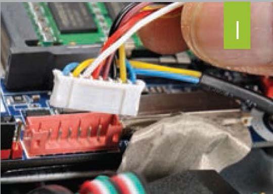
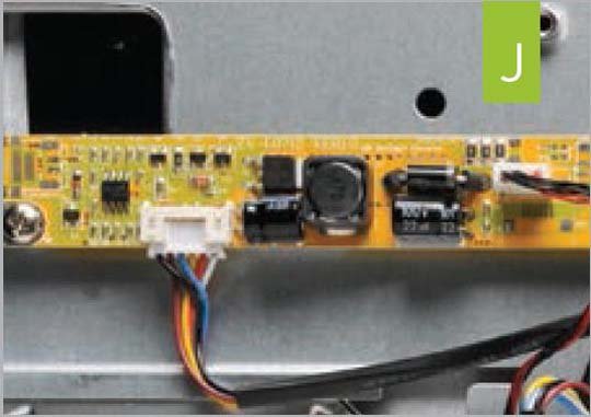
Unlike a Desktop monitor, which is powered by its own power brick or internal AC/DC device, the AiO needs to be powered from the motherboard. To do that you need to plug the 7-pin connector into the red header next to the LVDS connector (image I) . This is also keyed to only fit in one way and should snap into place. Once that’s done, follow the cable out to the end where you should find another connector. This gets plugged into the inverter board, which is the small orange, rectangular PCB to the left of the speaker (image J) .
8. Bring tht Noise
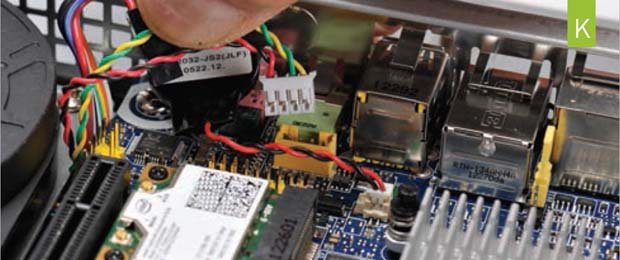
Again, Everything in the AiO uses internal headers rather than external ports. If you want to use the AiO’s internal speakers, you’ll need to plug them in using the 4-pin header located near the Wi-Fi card and CMOS battery (image K) . It’s keyed to only fit in one direction.
9. Connect Wi-Fi
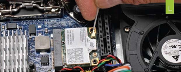
Some AIO units come with multiple antennas, but Loop chose a single antenna for this chassis. We won’t debate the wisdom of a single antenna, but it can create some confusion for newbs. Just look for the small gray antenna lead and plug it into the port labeled “Main 1” on the Wi-Fi card. It should snap into the socket with light pressure (image L) .
10. Set the Voltage
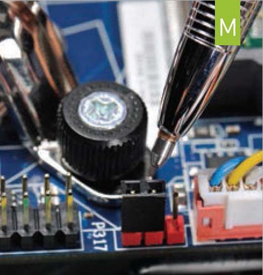
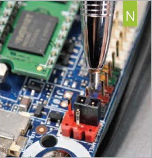
You need to configure the motherboard’s headers for the correct voltage. First, check the 3-pin header next to the “FPD Power” inverter header that you plugged in earlier. By default, it should be set to pins 2 and 3, or 19 volts, which is correct for the Loop (image M) . You’ll want to check the manuals for your AiO and your motherboard, as setting the voltage incorrectly can damage the inverter. You also need to set a secondary inverter header to the correct voltage. This header is located near the front-panel connector and should be set to pins 4 and 6, for 5 volts (image N) . This is the default position for the Intel motherboard and the correct voltage for the Loop.
11. Connect Final Plugs and Button up
You’ll also need to plug in the three USB headers as well as power and data cables for the optical drive and SSD, and you need to plug the SATA power cable into the motherboard. All that needs to be done now is to attach the back cover (while you plug the cover’s auxiliary fan into an open fan header) and attach the stand. Now, just plug in your power brick and fire her up!
12. Well, almost...
Intel’s Motherboard comes in an older rev, the G23736- 503, and a newer rev, the G23736-504. If your board is a 504 or up, drive on. If it’s older, you’ll need to update the BIOS because the older board defaults to external graphics rather than the LVDS connector. No worries, you can update the board by just dropping the latest BIOS from the Intel website in the root of a USB key, removing the jumper from the BIOS_CFG header, and booting the machine. The board should automatically update after two minutes. Once the rig’s blue system LED stops flashing, you can power down, replace the BIOS_CFG header, and move on. Even if you have the newer board, there is one setting you need to change. Go into the BIOS and then into the Video settings, and in the setting for All-in-One Chassis, set it to the chassis in use. In this case, it’s the LP-2150. It’s recommended that you then lock the settings so they can’t be changed without going into maintenance mode.
Click the next page to see the system's benchmarks!
The biggest gaming news, reviews and hardware deals
Keep up to date with the most important stories and the best deals, as picked by the PC Gamer team.
